Some basic info about the electrical system can be found here:
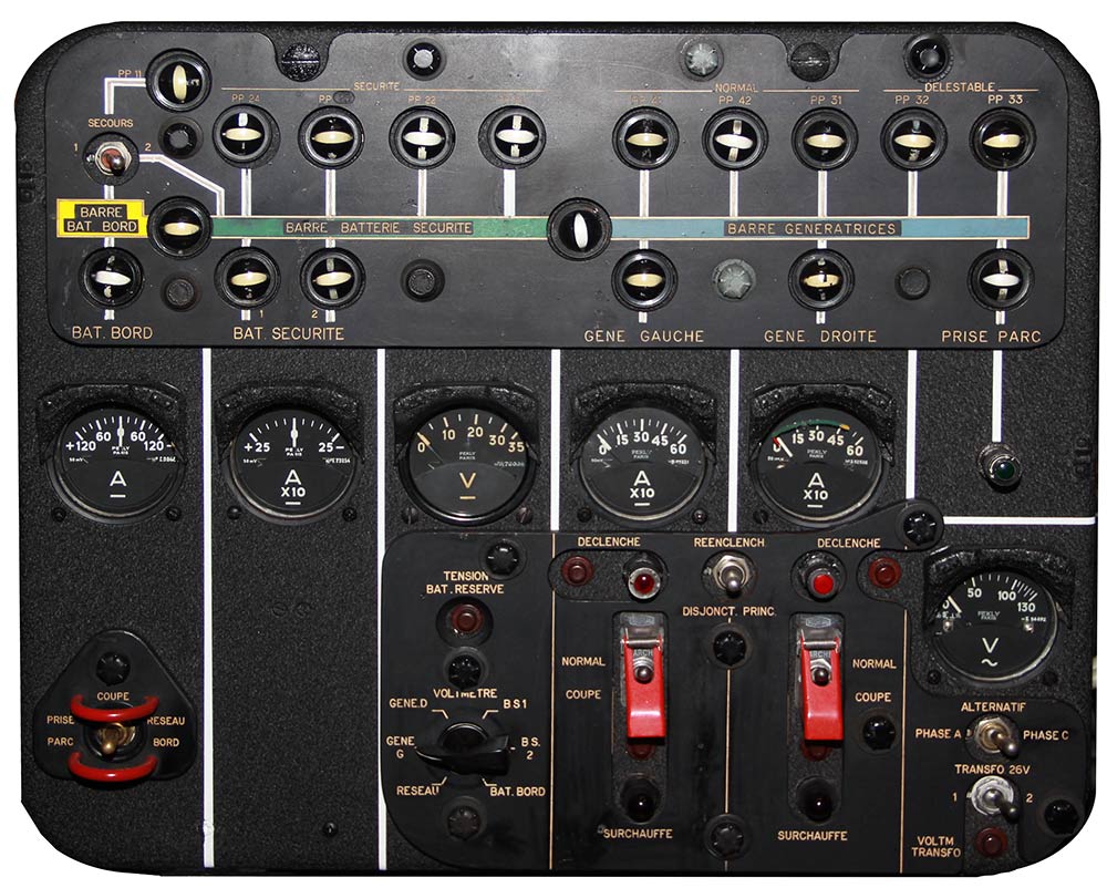
Battery selector switch
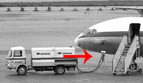
PRISE PARC (Ground Power): The aircraft's electrical systems are supplied by the ground power. BAT BORD (Normal battery) and BAT SECURITE (stand-by battery) are isolated. Generators cannot be connected. If the ground power exceeds 32V for more than 3 seconds it is disconnected.
COUPE (OFF): Aircraft's electrical system are de-energized.
RESEAU BORD (Plane Bat): BAT BORD (normal battery) is connected to bus PP11 1 and 2, starter system
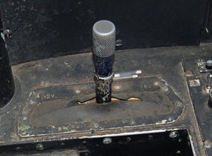
Still figuring out what that is...
Manuals do not provide adequate description.
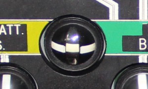
Magnetic Indicator normal battery
This magnetic indicator will show | when the switch below it set to "RESEAU BORD". The ammeter will show current being drawn.
Stand-by batteries
There are actually 5 stand-by batteries arranged in two groups with three batteries in one group and two in another. Total capacity is 80Ah. When the standby battery handle is in its normal 28V position, the batteries are connected in parallel. Each group will then be individually connected to the stand-by battery bus (PP2) provided the battery selector is in the RESEAU BORD position. These magnetic indicators show whether the batteries are connected. The batteries will either deliver power to ghe bus or be charge from the bus. On ground with the nose gear commpressed charging is limited by a resistor.
Normal Battery Bus
Also called PP1. It is connected to the normal battery, but will receive power from PP3 (Generator Bus) via PP2 (Stand-by Battery Bus) whenever PP3 is energized.
Stand-by Battery Bus
Also called PP2. It is connected to the stand-by batteries, but will receive power from PP3 (Generator Bus) whenever this bus is energized.
Generator Bus
Also called PP3. It is energized by the generators or on ground by the 28V DC ground power source. It can never be powered by any other DC power source.
Magnetic Indicator
Shows a line when the Generator Bus poweres the Stand-by Battery Bus.
Ammeter Normal Battery
The ammeter for the normal battery. This battery has a 16Ah capacity. In case of engine start with batteries this battery assures the igniters are powered.
Emergency Battery
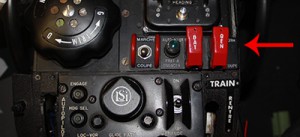
When this push button is depressed it indicates the voltage of the Emergency Battery (0.9Ah). It will be connected to PP17 and the emergency lights when the BAT switch on the pedestal (see above, it is the left one of the two in red) is in the OFF position. It is charged by inverter 1 or 2 through a transformer.
Voltage selector
Shows voltage of the selected system:
GENE. D : right generator
GENE. G : left generator
RESEAU : ground power
BAT.BORD normal battery
BS.1 stand-by battery 1
BS.2 stand-by battery 2
Voltmeter
Displays the voltage of the selected system.
PP33
If this magnetic indicators shows a line it means the following systems are powered:
- Waster water system
- Part of the cabin lights
PP32
If this bus powered, the following system are energized:
- Aft Galley
- Reading lights
- Aisle and toilet lights
- Razor outputs
- Water heating (right side)
- Some windshields
PP31
Powers the following systems:
- Panel lights
- Passenger entrance
- Left wing light
- Front water heater
- Angle of attack indicator
- Artifical feel
- Both cockpit ventilation fans
- Reading lights cockpit
- Part of the cabin lights
- Toilet lights
- UA panel lights
- Engine lights
- Copilot windhield heatings
- Ice detector
PP42
Powers the following systems:
- Flasher &. landing lights and motorCabin RH incand. light
- Radio panel light
- Instrument panel red lights
- VHF2, ADF2, Selcal, VOR2
- Tape reproducer & cockpit loudspeakers
- Flight director 2
- Normal inverter control
- ATC, DME1 (not installed on Poitou), DME2
PP41
Powers the following systems:
- Cpt outb. windsh. heat & windsh. wiper
- Anti-collision light
- Marker &. VOR I
- Alt. Inverter control
- Flight Director 1
- Ground power indicating light (test)
- Artifical feel pitot heat
- Radar
Left generator
Indicates whether the left engine's generator supplies the generator bus (PP3)
Right generator
Indicates whether the right generator supplies the Generator Bus (PP3)
Ground Power plugged in
When this lights illuminates green, the ground power is plugged in.
Magnetic Indicator ground power
Shows a line when the ground power is supplying the Generator bus (PP3). This is archived by switching the lower left switch of this panel to "PRISE DE PARC".
Left generator ammeter
Shows how much amps the generators puts out.
Right generator ammeter
Shows how much amps the generator puts out
Generator overheat warning
If a generator becomes overheated a thermos switch will close and activate the corresponding generator SURCHAUFFE (overheat) warning light together with the GENE master warning light and the chime. By placing the affected generator control switch in position OFF, the master warning light will go out and the chime be rearmed. The OVERHEAT warning light on the DC control panel will remain on as long as the overheat condition persists.
Each generator overheat warning circuit can be tested by depressing a TEST button located above each SURCHAUFFE warning light.
Generator reset switch
It is spring-loaded to centre-off position.
When actuated towards either generator tripped warning light, it will energize the reset coil of the corresponding generator main circuit breaker and bring the generator back online.
Generator control switches
The two generator control switches with positions ON (NORMALE) and OFF (COUPE) are located on the DC control panel and are placarded LH and RH DC GENERATORS. They control the main contactor of the respective generator. With a generator control switch in OFF position, the main contactor for the corresponding generator will always be open and the generator will be disconnected from PP3. With the switch in ON position, the
main contactor will be closed and the generator connected to the bus provided the generator functions normally and provided the throttle switch is closed and 28V DC ground power is not connected.
Transformer selector
Two transformer-rectifiers - TR1 and TR2 - are utilized for converting 115V AC power delivered by the engine driven alternators (or by a 115V AC ground power source) into 28V DC. The TRANSFO 26V switch is used to connect either one of the transformers to VP5. The switch has two positions labelled 1 and 2. VP5 for instance powers the control surface pos. indicator, fuel pressure and flap position indicator.
Inverter voltmeter
The voltmeter can be connected to VP3 or VP4 by placing the INVERTER VOLTAGE selector in position PHASE A or PHASE C
respectively. Many instrument gauges use 26V / 400hz.
Transformer Voltage
The voltmeter can also be connected to VP5 for check of the 115/26V transformer voltage . This is accomplished by depressing the VOLTM TRANSFO button located below the voltmeter.
Generator trip warning
This warning circuit will be energized whenever a generator main circuit breaker trips due to a failure in the generator system. The circuit will then activate the following warnings:
- The red warning light for the affected generator.
- The GENE master warning light and the chime.
A tripped main circuit breaker will also open the generator field circuit and the generator main contactor.
Generator voltage and load will drop to zero and the magnetic indicator will show that the generator has been disconnected from the bus.
The warning lights will go out and the chime will be rearmed when the corresponding generator control switch is placed in OFF position.
NOTE: It should be observed that the generator trip warning circuit will not be activated when the generator was manually disconnected. Voltage will be displayed however.
Generator trip warning test
Each generator trip warning circuit can be tested by depressing this button. the GENE warning light on UP5 will illuminate, a chime sound and the red warning light to the right of this button illuminate.
Ammeter stand-by batteries
Shows amperage drawn or delivered to the stand-by batteries.
PP21
Power the following systems:
LH airfoil de-Ice valve
De-icini duct temp. indicator
LH servodyne heating
Servodyne &. Brake chute comp. temp. lnd.
Servodyne overheat warning
Radio ventilation valve
Cockpit duct &. amb temp. ind.
LH oil temp. indicator
Ui Nozzle pos. indicator
LH Fuel press. and level warnings
LH main fuel pump No. 2
Forward entrance light
Door opening allowed light
PP22
Powers the following systems:
Airfoil half capacity relay
RH Airfoil de-ice valve
Airfoil de-Ice temp. control
Leading edge temp. indicator
OAT indicator
RH servodyne heat
Cabin duct & ambi. temp. indicators
Radio ventilation control
RH oil temp. indicator
RH nozzle pos. indicator
RH fuel press. and level warnings
RH main fuel pump No. 2
PP23
Powers the following systems:
VOR1
Glide Path 1
ADF 1
Radio lights
PP24
Powers the following systems:
VHF2
VOR2
Glide Path 2
ADF2
Radio lights
PP11 Essential Bus
Powers nearly everything - the list would be too long.
Magnetic Indicator
Shows a line when the stand-by battery bus poweres the normal battery bus.